
Cross-laminated timber (CLT) is taking center stage in a new Boston development set to break ground later this year. Placetailor’s 201 Hampden is a zero-carbon, full CLT, Passive House building that will be bringing 14 units of affordable and market-rate housing to Boston’s Dudley Square, with construction set to begin later in 2022. Placetailor’s development, architecture, and construction management divisions worked with Massachusetts Institute of Technology start-up Generate Technologies to provide the region with this exemplary mixed-income, mixed-use building.
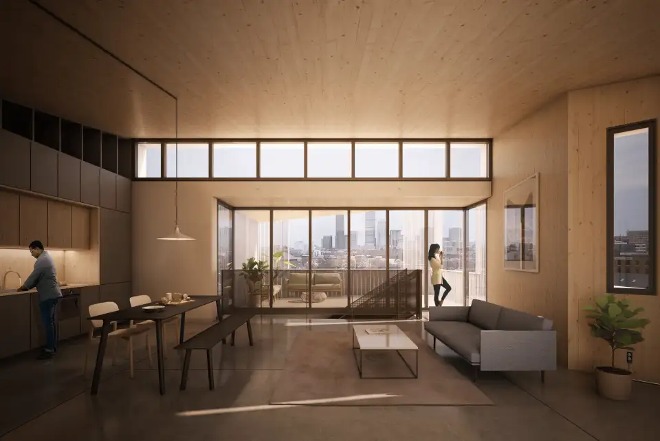
There are immense benefits to utilizing CLT, despite it being still in its infancy as a building material and its unfamiliarity to many building code officials. These benefits can be captured best through the lens of the triple bottom line concept, which explores a business’s or a product’s impacts on the planet, people, and profitability. Placetailor fused the triple bottom line concept and its dedication to Passive House design to forge its “Future Housing” practice.
Planet
The CLT utilized at 201 Hampden is processed using timber that is sustainably harvested in the United States. The raw material is manufactured into cross-laminated panels or strips of timber that are compressed together. For this particular project, the team is utilizing reclaimed eastern hemlock that was the recent victim of a blight; fire and structural testing are currently being done on the CLT panels made from this stock.
The nature of the material itself acts as a long-term carbon storage vessel. By utilizing CLT as the structural components of a building, the need for concrete and steel are eliminated, or greatly reduced. This material choice substantially lowered the carbon footprint at 201 Hampden, essentially turning the building into a carbon sink.
Additionally, CLT provides surprisingly beneficial thermal properties for exterior assemblies, aside from being a structural component. While the strict R-value is very low for timber, and is only R-6 per CLT panel in the typical wall assembly of this project, the thermal mass of mass timber reduces the amount of potential thermal bridging moments and helps normalize the interior temperatures. Consider a log cabin, which might only have an overall wall R-value of 6 but has helped many survive in cold climates. Thanks to the CLT and continuous exterior insulation layers, 201 Hampden will act like a next-generation log cabin. As an extra bonus, CLT’s thermal mass allows for minimizing the thickness of the exterior insulation, translating into less embodied carbon—while still adding up to a lower operational carbon footprint throughout the life of the building.
People
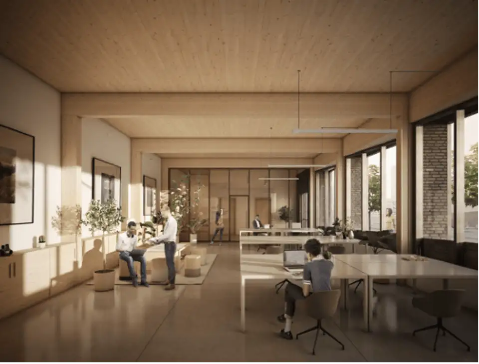
Biophilic design attests that humans have an innate desire to connect with nature or elements that remind us of natural settings. CLT, having a wood-grain texture and finish, will impact individuals by providing a visual and haptic sensation of being surrounded by woody plant species. Beyond having a soothing physical appearance, the material is healthy for the indoor environment. CLT is a safe material to interact with because it does not emit unsafe levels of volatile organic compounds (VOCs)—a critical requirement for achieving safe indoor air conditions and Phius certification. At 201 Hampden, the design team opted to expose the CLT structure to the indoor environment as much as possible. This choice reduced the need for additional materials and paint, which ultimately cuts back on the number of emitted VOCs.
Marginalized communities are often impacted more severely by the multiple crises of today, whether it’s the climate crisis, the health crisis, the housing crisis, or the displacement crisis caused by inequitable development. By utilizing a material such as CLT in a mixed-income project in the heart of Roxbury, we move closer to equitable growth in the neighborhood, creating a development where people of all socio-economic levels are able to benefit from CLT’s psychological and physiological benefits and participate in the proactive reduction in their carbon footprint.
Profit
CLT has proven itself as a beneficial building material for its constructability and ease of assembly. As mentioned previously, CLT can replace the need for other structural materials, when planned for properly. This reduces the need for more trades to be involved in a project, simplifying construction site coordination. The pre-fabricated panelized construction process expedites the project and cuts back on the overall timeline.
While this first foray into CLT has come with the cost of a learning curve for Placetailor, the lessons learned can be applied to taller buildings, where the CLT can replace typical steel construction with a considerably greater cost-effectiveness. During the course of design, the team has also been introduced to start-ups who are working to incentivize the selection of mass timber through brokering carbon credits. Economics drive so much, and so this financial connective tissue will no doubt prove invaluable for turning the construction industry toward carbon-neutral materials.
Future Housing
At Placetailor, we have been designing and building exclusively to Passive House, net zero-energy, or net zero-carbon standards for over a decade. We have found that the majority of people looking for a home are less concerned with a particular sustainability certification and instead are more concerned with whether their homes can facilitate their zero-carbon lifestyles. They want to know that it was developed with support from the community, by companies within the community, and by designers and builders from the community who are able to continue to live in the community. They want to know that it is healthy and comfortable. All of this, when achieved consistently at or below market rate, we refer to as Future Housing.
Phius has been a guiding star in our continual and evolving definition of Future Housing. The handful of critical principles and targets provide a clear path to not just lower energy use, but also to the ancillary benefits of health, comfort, and sound attenuation that round out the core of our Future Housing standard. (For those who are unfamiliar with Phius requirements, to achieve certification a project must comply with the U.S. EPA’s Energy Star and Indoor AirPLUS program requirements, as well as those of the U.S. DOE’s Zero Energy Ready Home program and the typical Passive House metrics.) So, while not every project of ours has been certified, every project has been within reach, and every project since our inception in 2008 has exceeded the AIA 2030 Challenge energy reduction targets.
Design Process
Our Future Housing starts at the project's conception, making sure clients and investors are aware of and on board with our mission to achieve Passive House standards. With open communication and understanding established, the design process begins. When 201 Hampden started the schematic design phase, our certified Passive House consultant (CPHC) reviewed Phius’s requirements with the project architect to ensure these would be incorporated early in the design process. Thorough energy modeling and analysis allow the design team to make informed decisions.
What follows is a procedural breakdown of Placetailor Elton Hampton Design’s (PTEH’s) integrated design process starting with preliminary analysis and ending with simulated energy modeling. For orientation, the project is located in Boston, Massachusetts, which is situated in climate zone 5. This is a heating-dominated climate with low outdoor humidity levels in the winter.
Preliminary Analysis
Steps 1 and 2, undertaken during the early analysis phase, can be performed without the need for energy modeling software, making it accessible to all. Steps 3 and 4 require light energy analysis software that is intuitive for an end-user to learn and implement.
Step 1. Analysis begins with volumetric and surface area calculations, specifically surface-to-volume ratios (SVR) and heat loss form factor (HLFF) calculations. SVR is a measure of massing volume efficiency of a building's design (see Figure 1). The calculation is performed by taking the sum of the entire building envelope and dividing it by the building's gross volume (envelope area / gross volume). The ideal target ratio range is from 0.24 to 0.3.
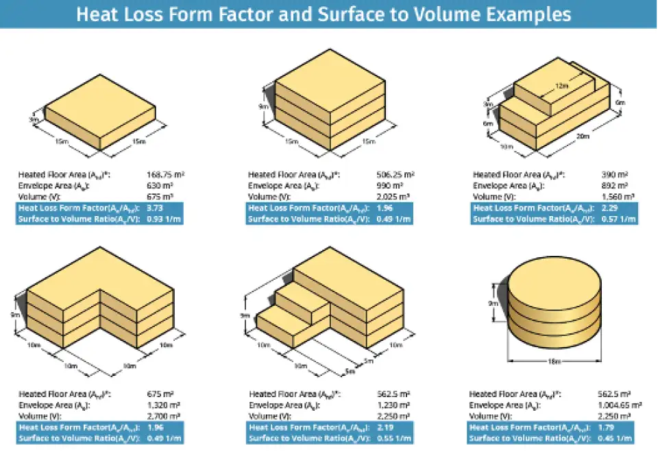
HLFF measures the compactness of a building. The more compact a building is, the less insulation is needed to achieve the building's energy reduction targets. Inversely, the less compact a building is, or the higher the HLFF, means that it is less efficient, and more insulation will be required. The calculation is performed by taking the interior conditioned floor area and dividing it by the sum of the building’s entire envelope area (iCFA / envelope area). The ideal target is equal to or less than a ratio of 2.5.
When these calculations were crunched for Hampden, the design failed to be within an acceptable range for SVR, but performed very well for the HLFF ratio.
These results signaled to the design team that Hampden has a good ratio of interior floor area to exterior envelope area, but that the shape of the building's volume is not efficient. Hampden is shaped like a triangle, which is one of the least efficient volumetric shapes. This means that the building will require more energy to heat and cool the space. Alternatively, additional upfront money can be spent on more robust assemblies and systems to compensate for this.

Step 2. Calculating a building's window-to-wall ratio is another accessible means of designing an efficient building. As a rule of thumb, it is ideal to target 18-20% of glazing to wall area across an entire building (see Figure 2). The amount of glazing recommended per façade orientation is dependent on the location, in addition to project type. If the project is located in a heating-dominant climate, it would be beneficial to install more windows on the south façade and fewer on the north. This will help to best utilize solar heat gain on the south façade and mitigate against heat loss on the north-facing façade. To hit the building’s energy reduction targets, the design team may need to specify different glazing solar heat gain coefficients (SHGCs) for individual facade orientations.
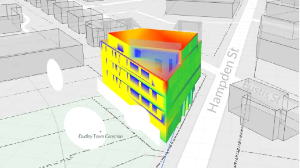
Step 3. This part of the energy analysis utilizes an Autodesk Revit plug-in called COVE.tool. Figure 3 is a solar exposure diagram showing the averaged amount of sun that a surface receives throughout the year. The green façade, which is east-facing, is receiving morning sunlight, yielding a 50% solar exposure rate. The southwest façade, which is mostly yellow in color, is experiencing mid-afternoon sun and is receiving 80% solar exposure. This analysis informed the design team that windows with a lower SHGC, such as 0.25, should be specified for the southwest façade to reduce the amount of solar heat gain.
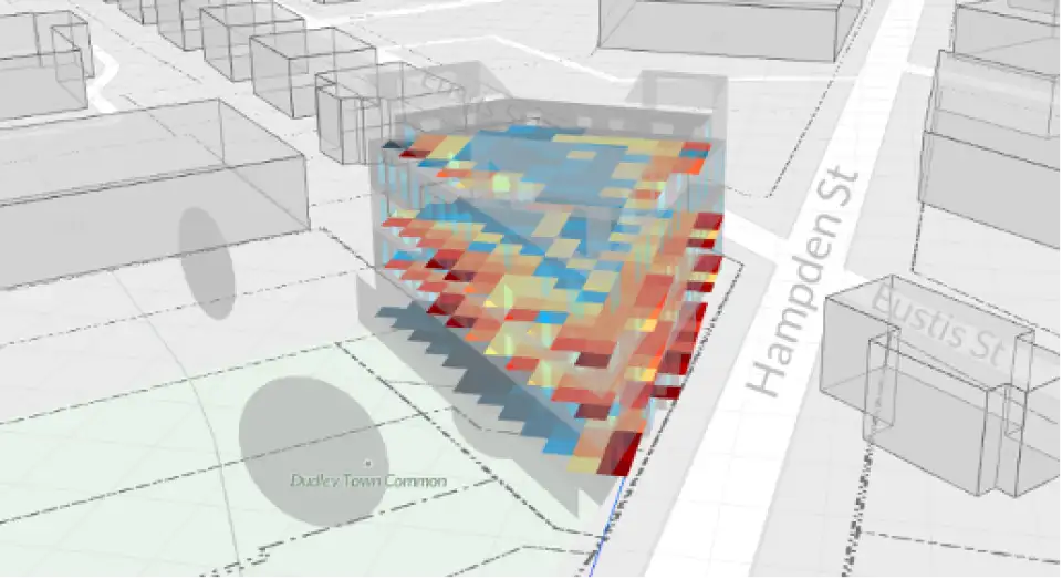
Figure 4 is a Spatial Daylight Autonomy diagram. It is showing visible light transmittance within the residential units. The floor area closest to the windows are receiving an uncomfortable amount of light, indicated by the red and orange tiles. This is suggesting the design team could reduce the overall glazing percentage and still maintain a comfortable amount of interior daylight. When indoor environments receive excessive light, fabrics can become sun bleached and surface glares can affect occupant comfort.
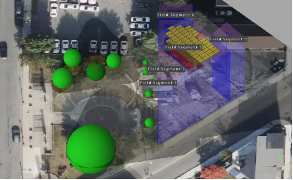
Step 4. This step consists of analyzing photovoltaic (PV) production on site. This is computed via an online software tool called Helioscope (see Figure 5). Oftentimes, with medium to large size multifamily projects, it won’t be possible to cover the entire building's energy usage with on-site solar. Such is the case for Hampden. In these cases, it’s good to target a PV output large enough to cover a building’s miscellaneous electrical loads.
Simulated Energy Modeling
Step 5. This phase of robust energy modeling starts in schematic design and continues into construction documentation. Energy modeling will sometimes extend into the construction administration phase, if there are change orders or value engineering efforts later in the project. PTEH utilizes WUFI Passive software for advanced analysis of hydrothermal conditions while also taking shading, daylight, and climate into account.
Before schematic design ends, the CPHC will conduct a feasibility study that models out three different case studies using WUFI. This allows a cross comparison of different assembly and mechanical, electrical, and plumbing (MEP) system options. The CPHC presents these options to the client and design team in a collaborative setting to weigh the pros and cons of each option.
Case 1. Code Minimum Design. The first energy model is built to the project’s local energy code minimum requirements. This provides the design team and client with a baseline understanding of how their building would perform if no Passive House concepts were taken into consideration.
Case 2. Architectural Drawing Set. The second WUFI case study will be modeled based on the architect’s narrative for assemblies and systems. Usually, the architect’s narrative meets or exceeds the minimum energy code requirements.
Case 3. Passive House. The last energy model is designed to Passive House certification. This takes the architect's design narrative and enhances it to hit the energy reduction targets.
The target energy reduction criteria specific for 201 Hampden are listed here. These numbers are determined by Phius and are customized for 201 Hampden’s design and location.
Hampden’s Passive House Target Design Criteria:
HEATING DEMAND: 4.6 kBtu/sf/yr
COOLING DEMAND: 5.4 kBtu/sf/yr
PEAK HEATING LOAD: 3.8 Btu/hr/sf
PEAK COOLING LOAD: 2.7 Btu/hr/sf
SOURCE ENERGY CONSUMPTION: 4,683 kWh/person /yr
Below is how Hampden performed under each of the three different case study scenarios. Green text indicates numbers that meet or exceed the Phius requirements, while red text indicates points of failure.
CASE 1 - Code Minimum Design
HEATING DEMAND: 6.75 kBtu/ft2yr
COOLING DEMAND: 2.64 kBtu/ft2yr
PEAK HEATING LOAD: 7.8 Btu/hr ft2
PEAK COOLING LOAD: 2.93 Btu/hr ft2
SOURCE ENERGY CONSUMPTION: 5,583 kWh/person /yr
CASE 2 - Architectural Drawing Set
HEATING DEMAND: 2.43 kBtu/ft2yr
COOLING DEMAND: 4.36 kBtu/ft2yr
PEAK HEATING LOAD: 3.89 Btu/hr ft2
PEAK COOLING LOAD: 3.12 Btu/hr ft2
SOURCE ENERGY CONSUMPTION: 3,667 kWh/person/yr (with PV installation)
CASE 3 - Passive House
HEATING DEMAND: 1.46 kBtu/ft2yr
COOLING DEMAND: 3.63 kBtu/ft2yr
PEAK HEATING LOAD: 3.24 Btu/hr ft2
PEAK COOLING LOAD: 2.59 Btu/hr ft
SOURCE ENERGY CONSUMPTION: 3,566 kWh/person yr (with PV installation)
201 Hampden performed well in the Case 2 scenario due to the architect and design team utilizing robust assembly and system assumptions. Therefore, very little had to change to satisfy Passive House criteria in Case 3. Updates to the architectural drawing set model to achieve Passive House included a reduction in the number of windows, a higher performing HVAC system, and minor changes in assembly R-values.
In many instances, energy modeling can be used as a cost savings tool by helping teams dial in on the exact amount of insulation and performance needed to hit their Passive house targets. For 201 Hampden, the project was able to reduce the overall amount of insulation and windows that the design team had originally specified, providing some cost savings.
Step 6 & beyond. With the feasibility study completed, the CPHC continues to collaborate with the architect and design team to best detail assemblies and building systems that maintain the Passive House criteria targets. Below are the current assumptions for 201 Hampden’s building envelope assemblies. Components are listed in order from outside to inside (see Figure 6).
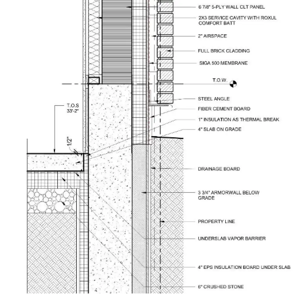
Slab on grade:
-Crushed stone
-4 inches of compression strength EPS rigid foam board
-Under slab vapor barrier (this also serves as the air barrier)
-4-inch concrete slab on grade, polished and sealed for final finish.
Foundation Wall:
-Drainage board
-below grade rated insulated sheathing w/ 3 inches of rigid insulation, taped at all seams (this serves as the air barrier)
-fluid applied waterproofing
-concrete foundation wall
-1 inch of interior EPS rigid insulation board between furring strips
-two layers of gypsum for fire rating.
Exterior Wall, Type 1:
-siding per elevation
-siding attachment system
-Insulated ZIP system w/ 3 inches of rigid insulation, taped at all seams (this serves as the air barrier)
-sheathing
-6 7/8-inch CLT panel
-2x3 interior service cavity w/ mineral wool insulation
-two layers of gypsum sheathing for fire rating.
Exterior Wall, Type 2:
-siding per elevation
-siding attachment system
-Insulated ZIP system w/ 3 inches of rigid insulation, taped at all seams (this serves as the air barrier)
-sheathing
-2x6 wood stud filled w/ mineral wool insulation
-1 3/8-inch air gap filled w/ mineral wool insulation
-2x3 service cavity w/ mineral wool insulation
-two layers of gypsum sheathing for fire rating.
Roof Assembly:
-TPO roofing membrane, welded at all seams.
-Underlayment board
-Tapered EPS insulation w/ 6.5 inches of buildup at the lowest point
-Continuous air barrier, taped at all seams
-6 7/8-inch CLT panel
Mechanical, Electrical, and Plumbing Systems
All systems are fully electric, as no gas will be utilized in this project.
Mechanical Ventilation System. Ventilation systems are required to be balanced, or within a 10% pressure difference as specified by Phius. The WUFI Passive energy modeling analysis informed the design team that a semi-centralized energy recovery ventilation (ERV) system would perform efficiently. In climate zone 5, ERVs are preferable to heat recovery ventilation (HRV) systems. This is due to an ERV’s ability to recirculate humidity back into the building instead of exhausting it all to the outdoors like an HRV would do. This capability is critical for maintaining occupant comfort in the heating months when the relative humidity is very low. When indoor air becomes too dry, occupants may begin to experience irritation to their nose, throat, and eyes.
In Figure 7, the yellow highlighted square is the ERV closet with ducted supply and exhaust runs shown to each unit and room. The ERVs are located along an exterior wall to reduce the intake and exhaust ducting to the outside. The shorter these runs can be, the more efficient the system will operate. Semi-centralized in this case means the project is installing one ERV per floor. This reduces vertical changes and the need for fire dampers within the building. It also allows for more efficient distribution and runs. The resulting cost savings can be spent on a higher performing ERV. We are specifying a Topvex TR800 with MERV 13 filters for the supply air and MERV 9 for the exhaust air. Topvex TR800 is AHRI and CAS certified.
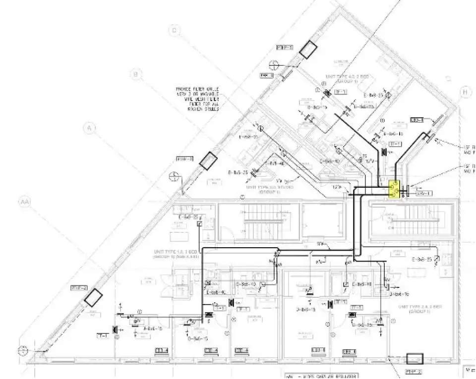
Mechanical Heating and Cooling System. A thermostat is required in each residential unit to control the heating and cooling systems, allowing for greater occupancy comfort and reducing wasteful heating and cooling. At Hampden we are specifying a decentralized system, with one Ephoca heat pump per residential unit (see Figure 8). The heat pumps will be placed in the common area of the units, such as in the living room. In order to provide heated and cooled air to the bedrooms, all bedroom doors will be undercut by ¾ inches to allow air flow. In addition to undercutting doors, jump ducts will be installed leading to each bedroom. The jump duct fans will be tied to the bedroom thermostats and kick on when room temperatures are above or below the thermostat setpoint. This method reduces the need for additional heat pumps per bedroom.
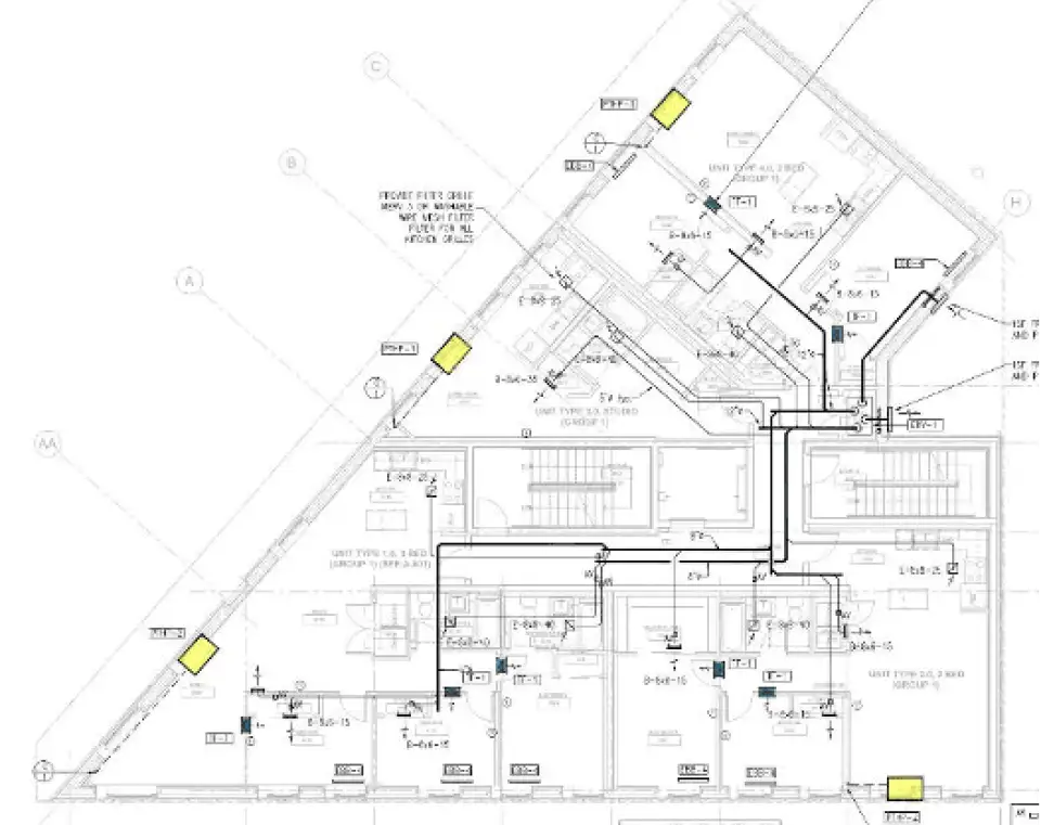
Plumbing System. The team opted for a centralized domestic hot water system with heat pump heating and storage tanks. Due to the restricting floor plan layouts, there is not enough room in each individual unit to accommodate a decentralized system. The design team specified the SanCo2 heat pump water heater. There will be four 119-gallon storage tanks on the ground floor in a conditioned storage room, as indicated by the yellow circles in Figure 9. The yellow highlighted rectangles are the exterior heat pump condensers. This system utilizes a CO2 refrigerant line, which reduces system heat loss and has a low global warming potential. This system is Energy Star rated and has a heating coefficient of performance (COP) of 2.8 - 5.5, depending on the outdoor temperature.

Looking Ahead
The integrated team committed to the use of CLT in order to learn and demonstrate—just as we have in previous explorations of materials, means, and methods used in prior Future Housing projects. While there was a cost to the learning curve, there are clear benefits to its application on other current and future projects. Particularly for high-rise housing, CLT is now a go-to material for the team, because the economics make it cost competitive with a steel structure. The typically smaller spans for residential spaces also provide opportunities to reduce the floor-to-floor heights without sacrificing ceiling height.
The project has yet to be built, and there will no doubt be more lessons to learn before its completion. For the sake of our mission—to facilitate the rapid transformation of all housing to zero-carbon Future Housing—the team looks forward to sharing each and every one for the benefit of all the other teams out there.
—Liz Hauver is a CPHC and the energy design manager at PTEH.
Project Team:
Developer: Evan Smith, Director of Placetailor Real Estate Development
Architecture: Placetailor Elton Hampton Design
Principal-in-charge: Bruce Hampton AIA
Project Manager: Juliet Borja AIA
CPHC / Energy Designer: Elizabeth Hauver
Project Designers: Mike Marotta RA, Sam Naylor RA
Design Consultant: Generate Technologies
Structural Engineer: Studio NYL
MEP Engineer: Zade Engineering
Civil Engineer: Merrill Engineering
Construction Manager: Felipe Francisco RA, PT Build