The Passive House standard was developed with the intent of designing and constructing buildings whose space heating load would be small enough that it could be entirely met through the ventilation supply air required for adequate indoor air quality. Early examples, including the Stadtwerke Hannover Passive House estate in Hannover, conclusively demonstrated that this goal can be achieved in practice.
A Novel Approach to Meeting Passive House Cooling Loads
As Passive House expanded into warmer climates, this goal was expanded to include meeting the entire space conditioning load—heating and cooling—via the ventilation supply air. However, delivery temperatures of around 14 °C (57 °F) limit the cooling capacity of the ventilation supply air to a level that is generally inadequate for this purpose. To increase the cooling capacity, it is theoretically and practically possible to reduce the supply air temperature. Indeed, the American Society of Heating, Refrigerating and Air-Conditioning Engineers (ASHRAE) has developed a designer’s guide to cold air distribution (CAD) [Kirkpatrick 2016], a cooling strategy to which ventilation supply air cooling belongs.
To date, CAD has been applied to industrial and commercial buildings. However, mechanical designers are uncomfortable adopting such an approach for residential buildings, due to three primary concerns:
The risk of condensation on the diffuser, caused by an indoor dewpoint temperature that is higher than the colder supply air temperature;
The risk of occupant discomfort, due to improper mixing of supply air and room air, leading to air dumping and cold drafts; and
The risk of mold growth on the interior finish in the vicinity of the diffuser due to reduced surface temperatures.
With funding support from the Canadian Mortgage and Housing Corporation, our team at Peel Passive House Consulting has undertaken laboratory experiments to determine under what conditions CAD is feasible in residential buildings.
Experimental Design
An instrumented apartment bedroom mock-up was created within two identical test chambers located within a rooftop test facility of the University of Toronto. The mock-up was intended to represent a typical residential apartment room, with a volume of 1.9 m deep by 2.44 m long by 2.47 m high, within the 3 m by 3 m by 3 m test chamber. It has a window and is insulated to Passive House levels.
The investigation examined the influence of the following key parameters on the previously described concerns.
Supply air flow rate. Three flow rates representing low (~20 m³/h), medium (~60 m³/h), and high (~90-120 m³/h) supply air settings were tested, as well as differently sized rooms. The high setting was originally set at 120 m³/h but proved to be far too high for the small room and was subsequently reduced to 90 m³/h.
Supply air velocity. The velocity influences how far the air travels into the room and the degree of mixing.
Diffuser type. Some diffusers were made of proprietary materials promising no condensation at low temperatures. Some were designed to induce high levels of mixing with room air. One was composed entirely of insulation to mitigate condensation. One was a conventional diffuser available at local hardware stores.
Diffuser location. We investigated both wall-mounted and ceiling-mounted locations. For the wall-mounted installation, the diffusers were positioned 200 mm below the ceiling to take advantage of the Coandă effect, which encourages air to entrain along the ceiling and mix with room air.
Insulation thickness. Experimenting with both 1-inch and 2-inch thicknesses, we tested how these impact the supply air temperature.
Air and vapour sealing. We compared the effects of perfectly sealed and imperfectly sealed distribution systems.
Diffuser coating. Anti-condensation paint was applied to some diffusers.
Position in room. We examined if, and how, the level of comfort varied around the room. The rationale for including this experiment was that, even if occupant comfort was not fully achieved with CAD, but comfort was improved over typical practice, then it would not stand as a reason against implementing it in residential buildings.
Results
After extensive testing, a number of diffuser strategies were identified that can safely deliver a super-chilled supply air while mitigating the three risks.
Only a wall-mounted solution can ensure occupant comfort (see Table 1). The ceiling-mounted diffusers could not consistently meet the occupant comfort criteria. For instance, one wall-mounted slot diffuser, set at a medium flow rate, achieved ISO 7730 Category A (highest rating) in two of the three test locations in the room, with the third position just barely missing this category. In contrast, one ceiling-mounted diffuser had two Category A locations, and one Category C, at a medium flow rate.

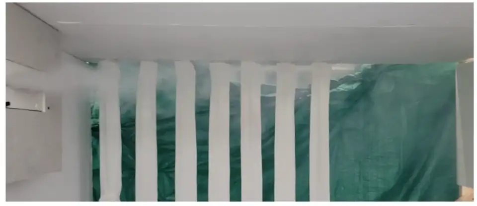
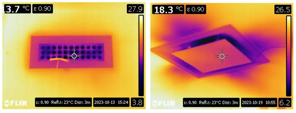
The diffusers designed to induce mixing with room air performed the best, as confirmed by infrared camera images and a fog test (see Figures 1 and 2).
A high supply air velocity tends to lead to a high room air velocity, especially at high flow rates. This issue is exacerbated by the small room, which leads to the airstream hitting the back wall and being redirected towards the floor. Table 2 shows the influence of supply air velocity on the room air velocity and the ISO 7730 Category. A velocity of no more than 3 m/s is sufficient for good air mixing in both bedrooms and living rooms in multi-family suites while avoiding high room air velocities. However, it is likely beneficial to adjust the airspeed based on the actual room depth.

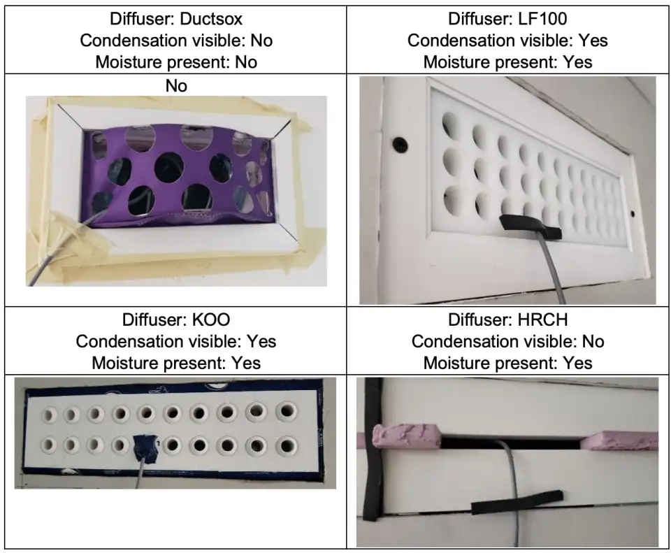
Only one of the diffusers made of a proprietary material prevented moisture from accumulating (see Figure 3). This moisture accumulation did not always lead to condensation but could potentially pose an issue for mold growth. Long-term testing would be required to verify this.
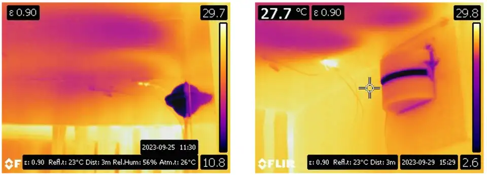
The anti-condensation paint successfully prevented condensation from forming on some diffusers. However, the paint must be applied consistently to a minimum thickness in order to work (see Figure 4). Our results suggest it should be factory applied. There is also a risk of the paint being scratched off (intentionally or unintentionally).
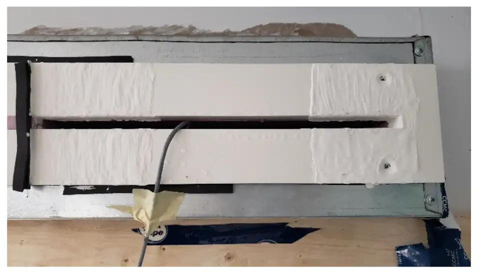
If not relying on special anti-condensation paint, the entire inside surface of the diffuser must be insulated with an insulation that has a minimum R-value of 7.2.
Condensation inevitably forms on any object directly in the line of the airflow that is exposed to room air (such as a sensor cable, diffuser framing, tape, etc.). See Figure 5.

Any air leakage around the diffuser inevitably leads to a cold surface temperature and potential condensation at these locations (see Figure 6).
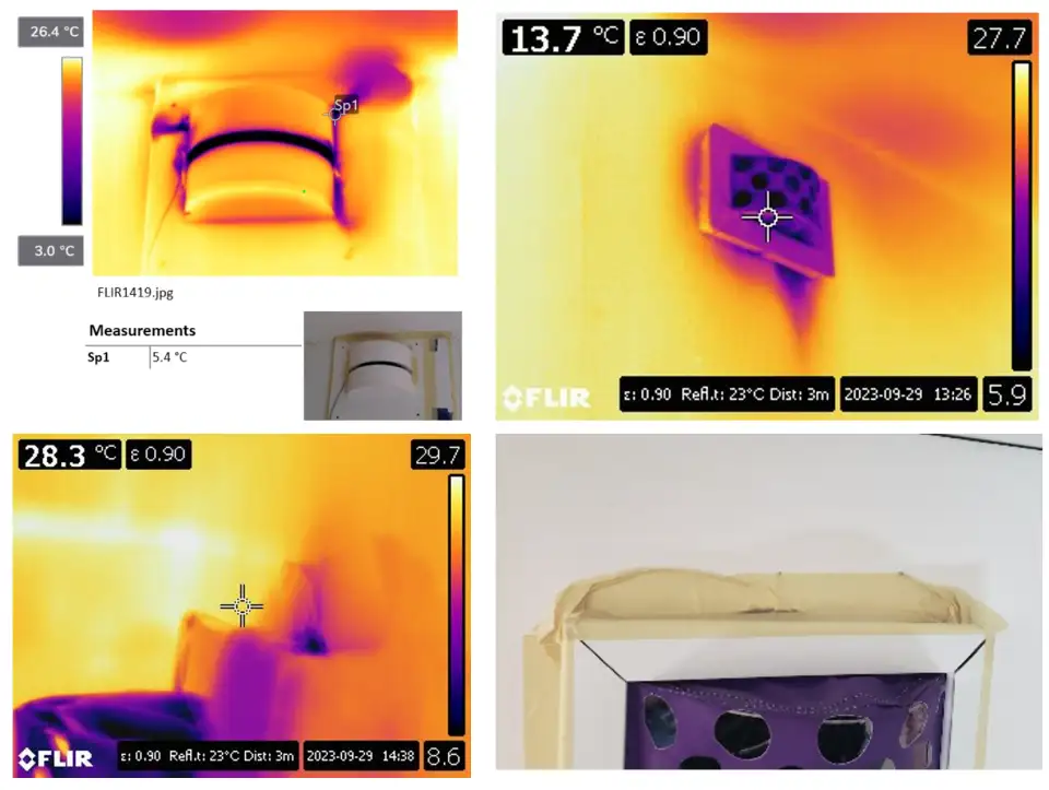
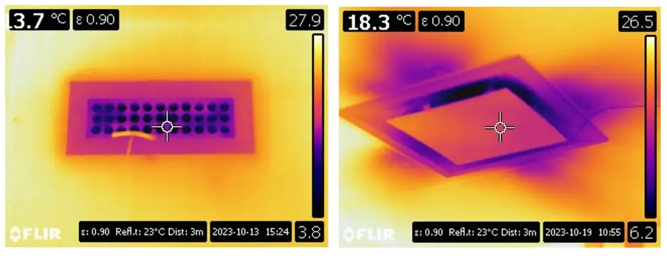
Any gap in the duct insulation or vapor barrier inevitably leads to condensation (see Figure 7).
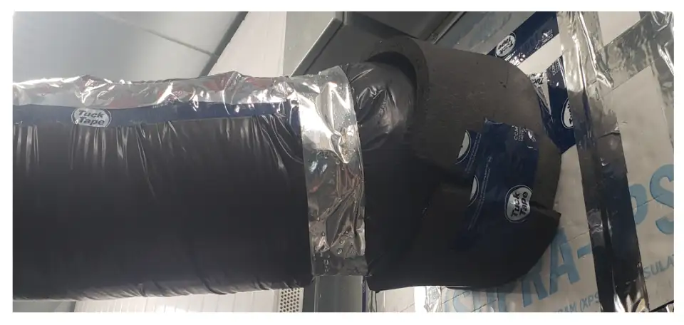
The size and insulation level of the supply air duct heavily influences the temperature of the air leaving the diffuser. Large ducts gain too much heat, which no amount of exterior applied insulation can address, due to the increased surface area. Indeed, we had to apply interior insulation with the lab’s existing ducting to achieve the target supply air temperature (see Figure 8). Likewise, insufficient insulation thickness leads to too much heat gain. All ducts must be insulated with 1-2 inches of fiberglass-equivalent insulation, depending on duct layout (see Figure 9).
Design and Implementation Recommendations
Based on the experimental results, the following recommendations can be made for design and implementation of CAD in residential buildings.
Right-sized ducting must be chosen for each branch of the duct network to minimize heat gain.
The entire supply air duct network from cooling coil to diffuser—and including the supply air VAV dampers—must be continuously insulated and vapor sealed to avoid condensation and mold growth risk. Where possible, install components upstream of the cooling coil.
Insulation with k = 0.036 W/(mK) should be 50 mm thick on ducting outside the dwelling units and 25 mm thick on ducting within the dwelling units. For long duct runs (>5 m), consider specifying 50 mm to ensure sufficient cooling is delivered to the intended space.
The attention to detail that is required is much higher than in conventional building. Providing training for, and working closely with, the construcion managers and HVAC contractors are essential to ensure the execution is of high quality. The ducting must also be tested to ensure it is airtight.
Pre-insulated duct components or components entirely comprised of insulation are potential means of mitigating poor workmanship by mechanical contractors, which is unfortunately commonplace in Canada. Friction-fitted, expanded propylene foam duct components, which are typically used for ventilation cold air ducts, offer good potential at reasonable cost.
Anti-condensation paint must be applied to the minimum thickness recommended by the manufacturer and is only suitable where the diffuser is not susceptible to damage during installation, commissioning, or operation.
Diffusers must be sized to ensure a minimum and maximum supply air velocity matched to the range of airflows they will deliver to ensure good air mixing and to avoid high room air velocities. The target velocity range depends on the room size but is likely not to exceed 3 m/s for typical apartment sizes.
The heat pump chosen for the project must be capable of generating chilled water down to around 1°C (34 oF). Most of the limited selection of air-to-water heat pumps on the Canadian market are currently not designed for this. The manufacturer may require glycol to avoid freezing, which could impact component specifications and maintenance effort and costs.
Conclusion
Experimental work has confirmed that there are viable approaches to CAD in residential buildings that mitigate the three key risks: occupant discomfort, condensation, and mold growth. The next phase is to implement CAD in an actual building, based on the design and implementation recommendations. Peel Passive House has received further funding from the Canadian Mortgage and Housing Corporation to implement CAD in a few residential building projects in Canada. Beyond implementation, substantial product development is required to develop pre-insulated duct components that mitigate common implementation issues with contractors as well as heat pumps that can generate chilled water down to 1 oC (34 oF).
This innovative solution is a funding recipient of Phases 2 and 3 of the Building for the Future Round of the Housing Supply Challenge. This challenge, administered by Canada Mortgage and Housing Corporation, seeks to remove barriers to housing supply in Canada.
References
[Kirkpatrick 1996] Kirkpatrick, A et al: Cold Air Distribution System Design Guide. American Society for Heating, Refrigerating, and Air Conditioning Engineers, Atlanta, 1996.