ph accelerator images pdfs page 01 1721352742

Drawing Passive House Details: From Sketch to Construction

Larry Weintraub at Appel Design Group, a friend and professional colleague, reached out to us at BluPath Design for help with a project that had serious sustainability, energy efficiency, and performance goals. After meeting with Bill Bardin, the project owner, and interviewing him using our Values and Goals worksheet, we decided this project would be a good fit for us. 
We developed the Values and Goals worksheet to facilitate an initial conversation about the client’s values and how they drive the goals of a project. We have a nuanced conversation with the client on many big-picture issues—health, low-carbon design, water conservation, beauty, certification and public recognition, energy efficiency, cost, comfort, and more—before we focus on practical issues like countertops and the number of bathrooms. Their priorities are the touchstone for future decisions as we develop sustainability strategies and set the level of performance for the project. 

As Bardin described the attributes of the house he wanted, all signs pointed to a Passive House—an important consideration for us, as our firm is focused on high-performance and Passive House projects. He confirmed our assessment with his own research, deciding that what he wanted was to live in a certified Passive House. The Bardin Residence is currently Design Certified under Phius CORE 2021. Construction is ongoing, with full certification expected in Fall 2024. 

BluPath Design (BP) helped put the design and construction team together.

  • Larry Weintraub, Appel Design Group, is the designer and architect of record (ADG).

  • Ilka Cassidy and Steve Hessler, Holzraum Systems (HZR), developed the factory-fabricated wall and roof panel system. Ilka is the energy modeler and, with Laura Blau, is the project’s Phius certification coordinator and administrator. Ilka also coordinated the factory permit review process.

  • HZR added New Energy Works (NEW), a timber frame and panelized high-performance enclosure fabricator and installer.

  • BP vetted potential general contractors, looking for a trained Passive House builder, and found Steve Vanadia at Vanco Construction. Vanco is known for building high-end houses. Steve and construction superintendent Ken Sybel took the Passive House builder training for this project. Vanco added their subcontractors to the construction team.

  • BP provided project coordination and team building, Passive House consulting and coordination, and architectural support.

We were excited to combine the unusual—for us—attributes of site-built floors and load path with factory-built walls and roof panels. The Barn, an accessory building and pool house on the site, combines the same assemblies with a timber-frame structure. 

We show the approximate workflow in the following drawings, but the complexities of remotely coordinating trades, expertise, and scope of work all contributed to creating a non-linear process. However, we all shared and worked together on achieving our overarching goals. BP prepared the architectural details with the following goals:

  • delineate the scope of work for clarity and pricing,

  • explain and document architectural design intent and materials,

  • show building code compliance,

  • coordinate the relationships between components and assemblies for construction and certification, and

  • demonstrate how Passive House performance and certification will be achieved.

Drawings
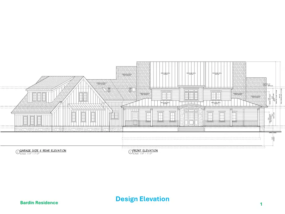
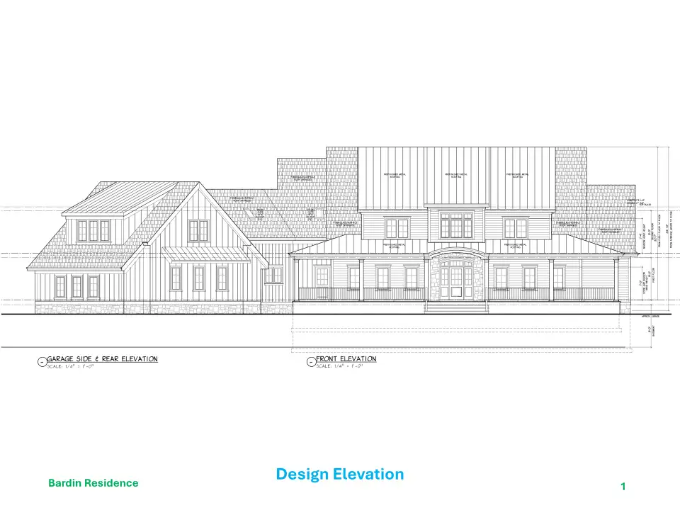
Figure 1 - ADG was the design architect initially engaged by the owner. They are not Passive House architects, but they know their way around the traditional style the owner expects.
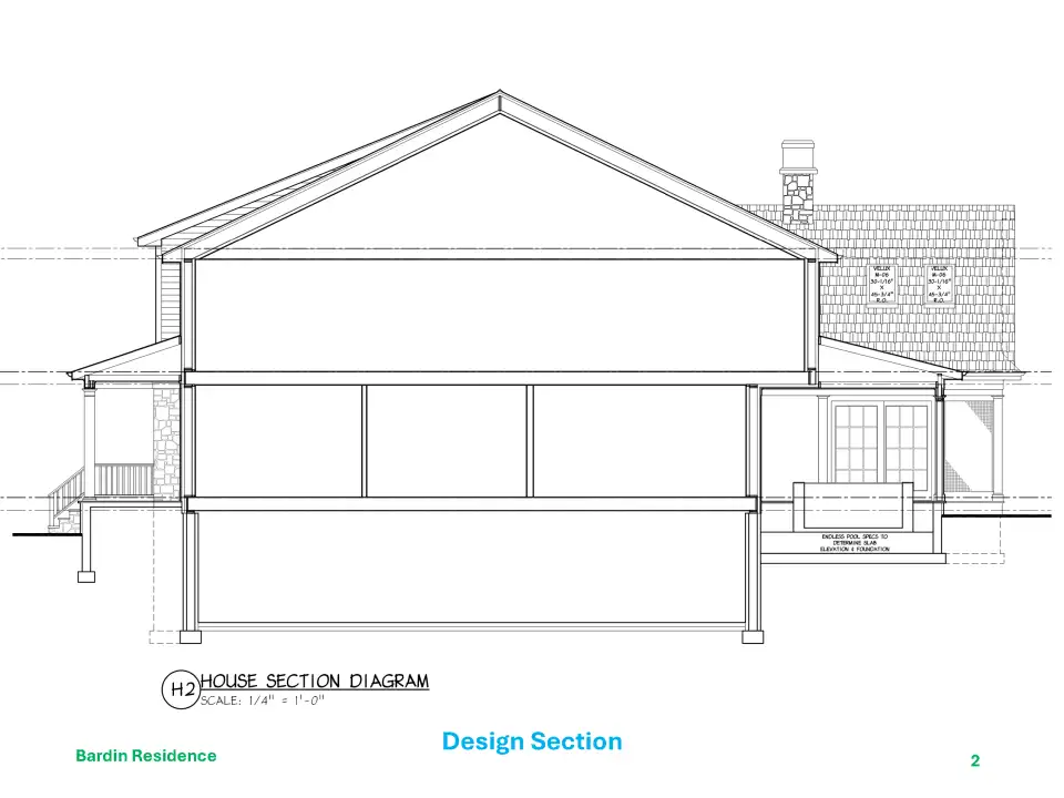
Figure 2 - ADG’s early design sections show the basic layout of the spaces.
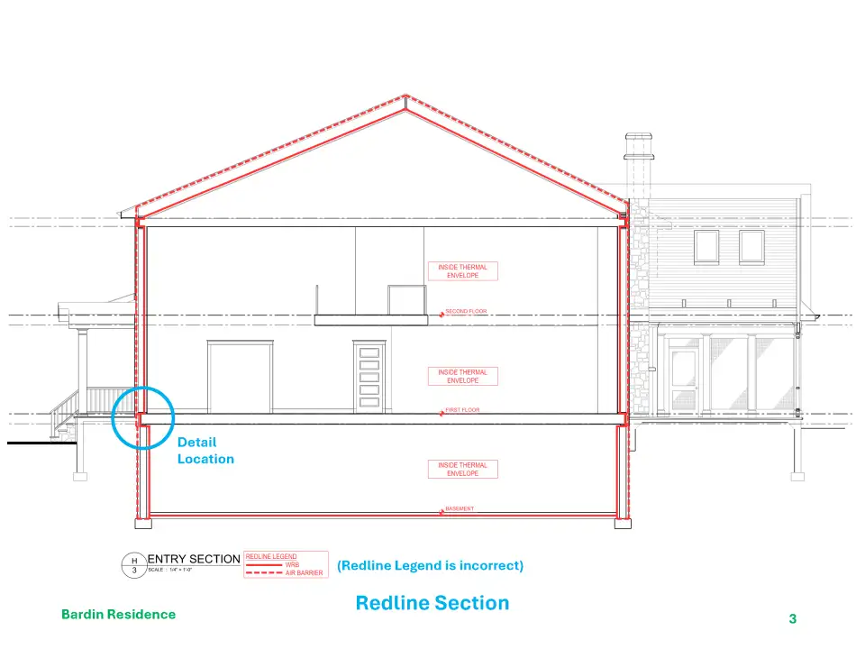
Figure 3 - BP delineated the redline air barrier, defining the thermal envelope.
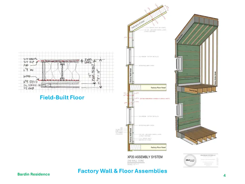
Figure 4 - HZR developed the off-site fabricated wall and roof panels, which are wood-based, vapor-open, airtight, low-carbon rainscreen assemblies. Site-built super-insulated air-tight floors use a similar approach. ICF foundations complete the envelope.
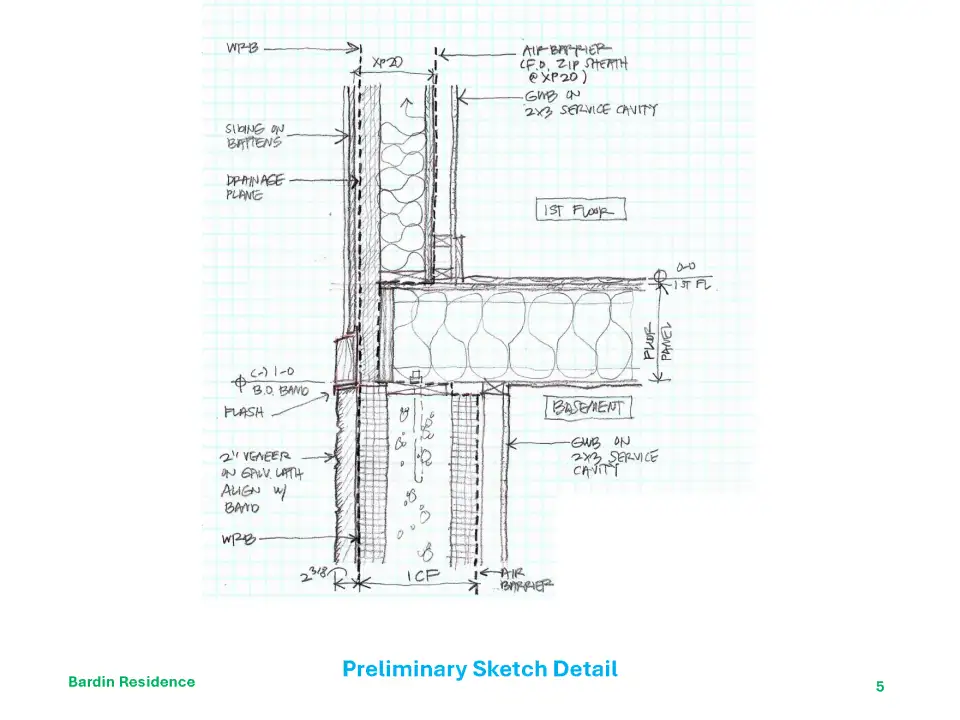
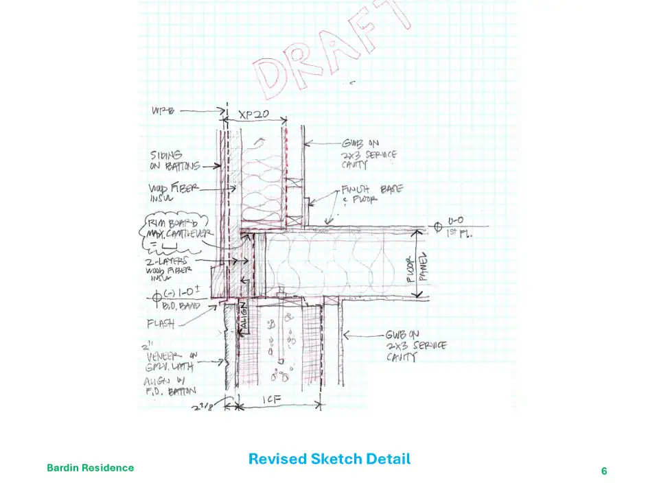
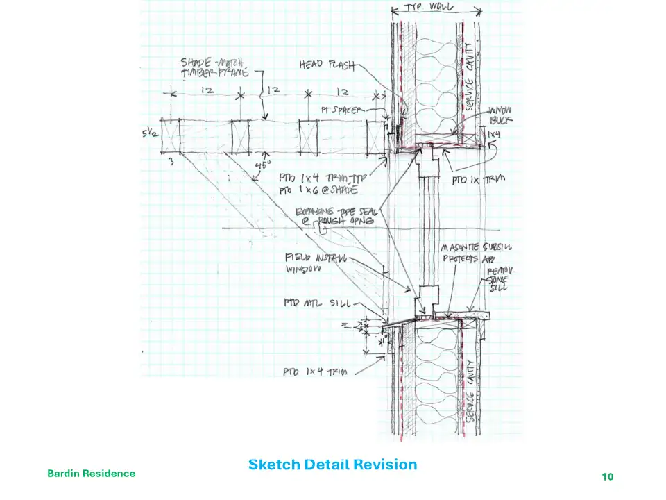
Figure 5 - BP sketched details to start integrating the systems and defining the scope of work for the trades.
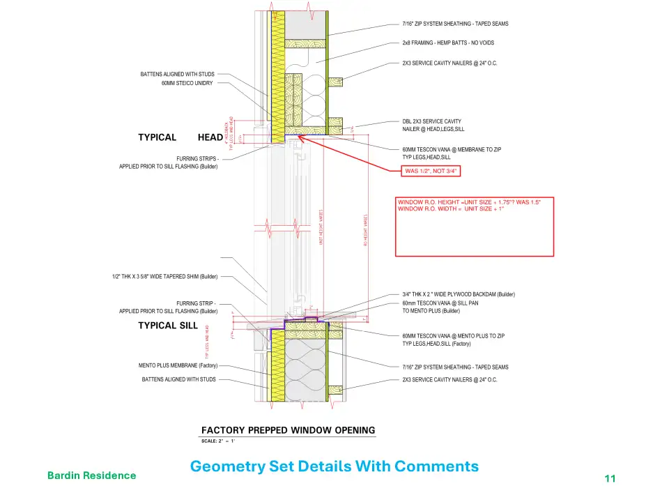
Figure 6 - With input from the rest of the team, BP revised and further developed the details to ensure performance while meeting the aesthetic intention. ADG, HZR, NEW, and Vanco added their combined intelligence and experience with comments on constructability.
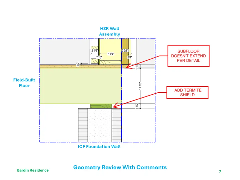
Figure 7 - Concurrently, HZR was constructing a digital model of the building to identify tricky air sealing and construction intersections, while also designing and defining all the wall and roof panels. The whole team reviewed the geometry model. BP and HZR met a few times to fly through the 3D model to identify difficult transitions and focus on maintaining the continuous insulation and air barrier.
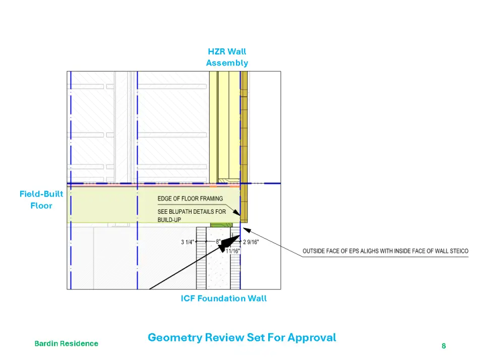
Figure 8 - The revised geometry model incorporates review comments and is submitted to the whole team for approval.
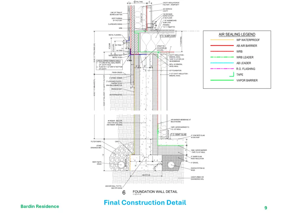
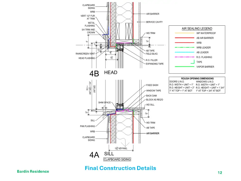
Figure 9 - The final construction detail shows all the components and how they come together. At this point, the trades have defined their scope of work, and the GC knows how they are integrated. BP developed the Air Sealing legend to clarify the air barrier locations, materials, and connections. This is the redline air barrier under a microscope.
Figure 10 - Of course, walls have windows and doors, and the sketches define how those openings are made airtight with continuous insulation and minimal thermal bridging. ADG commented on the design intent and structure, Vanco talked about constructability, and HZR managed the panelized opening. The window sizes and rough openings were finalized during this review. Note the shade is for the Barn, not the house.
Figure 11 - The 3D geometry model focuses on the successful window installation in the wall panel. BP comments show rough opening sizes are still in flux. Windows are site installed in the factory-prepped openings.
Figure 12 - Construction details coordinate the panel construction, continuous air barrier, water management, and architectural design, materials, and detailing. BP added the Rough Opening information as a reminder, mostly to ourselves, about the window and door assumptions worked out with the window installers.

These drawings integrate the thermal envelope assemblies—factory-fabricated wall and roof panels, ICF foundations, and site-built PH floors—and ensure a buildable, continuous air barrier. They are included in the building permit set for the architect of record and are submitted to Phius for certification. They coordinate the scope of work, facilitate the work between trades, show code compliance, and define the architectural details for the contractor. Ultimately, we translate the design intention and concept into drawings that the contractor can build to achieve the performance, usefulness, durability, and aesthetics of a certified Passive House.

Every project has its challenges and rewards and is an opportunity to learn new ways to design, document, and construct high-performance buildings. Using factory-built assemblies pushes big decisions early in the design process, including:

  • assembling the construction team,

  • determining the project delivery method,

  • ordering long lead time items such as windows and doors,

  • documenting and coordinating architectural and mechanical design, and

  • coordinating additional or ‘out of sequence’ tasks such as inspections for factory work by third-party inspection agencies.

Factory-built assemblies can allow construction in the field and the factory to overlap, reducing overall construction time and cost. There was some overlap in this project, and the panels and site work came together beautifully, a testament to the quality design and amazing builders.

Author: Paul Thompson
Categories: Article, Pre-Fab