This post is authored by Baxt Ingui Architects and John Mitchell of bldgtyp.
In our last post, we explored the general exterior wall details that make up a significant portion of the Passive exterior envelope. With this next installment, we look specifically at some of the details that make up the remainder of these walls. One challenge is installing a continuous air barrier between the floor plates and exterior walls at each level.
It is important to note that the priority in this detail is connecting the floor plate diaphragm (the assembly of joists, continuous blocking and subfloor) and the exterior masonry wall together. Structurally, this is vital to support an otherwise tall and unstable masonry wall. In typical construction projects, this is done by securing the first joist directly to the front wall and then attaching the subfloor to that joist. Next, solid blocking is installed between the first and second joists. Lastly, blocking is added throughout the floor plate, which results in a stabilized horizontal plane. This works well in a typical construction, but in a Passive house, we need to work in an air barrier and eliminate thermal bridging. The main conflict here is how to tie the front wall to the floor plate with an uninterrupted air barrier inside the masonry wall, from ground to roof.
The detail shown below was developed in an iterative way during some our first passive projects. D’Huy Engineering is a structural design engineer that has worked with us on many projects; Pete Garland and his team were vital in creating a detail that accomplished its structural duties while air sealing in an efficient and effective manner.
We learned very early that connecting the floor plate in the typical manner presented a host of issues and potential air infiltration points. Having to seal around blocking was difficult and connecting from the underside of the floor plate to the wall framing above was next to impossible.
Get Articles Like This Delivered to Your Inbox
Subscribe Now
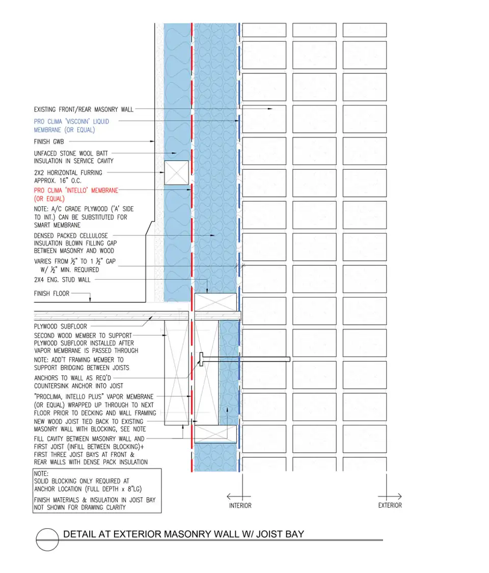
The air sealing and vapor control application is something we pay close attention to and has evolved as we build and reevaluate our details. In the project that is the case study for this detail, there are a few key sequencing points, starting from the exterior:
1. Air Barrier. On this masonry retrofit project, we installed the air barrier directly to the interior side of the exposed masonry walls. This allowed us to install an airtight layer early in the project and make durable, airtight connections at joist penetrations. As an added benefit, the liquid applied product safeguards against water leaking into the assembly through cracks or imperfect flashing and finding its way into the cellulose layer of the wall assembly, though it is not specifically labeled for this purpose. Once the existing masonry walls have been repaired/pointed and parged, the first step is to install the liquid applied air barrier (in this case Pro Clima Visconn) to the interior of all of the masonry walls, taking care to address any joist or other penetrations.
2. Blocking/insulation at wall. Instead of bolting the first joist directly to the masonry wall as is typical in masonry retrofits, we install the first joist in such a way as to minimize thermal bridging and create a connection path for the vapor retarder which will be installed over the wall framing and insulation. The first joist is separated from the masonry wall by 2” rigid foam, with solid blocking replacing the foam at the bolt locations specified by the engineer. While not thermal bridge free, this detail performs very well and satisfies the structural, thermal, and airtightness requirements of the project. In fact, it’s very similar to a detail you might use for a deck ledger on a house with exterior insulation.
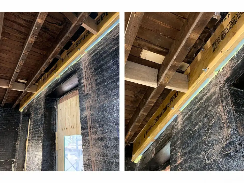
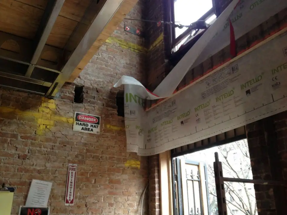
3. The Vapor Retarder. Since we’ll be insulating this wall on the interior side of the air barrier, the assembly needs a vapor retarder – the old adage of vapor retarder on the “winter warm side” still holds true in a Passive House. We use variable permeance (“smart”) vapor retarders where we can as they keep interior moisture out of the wall assembly in winter while allowing drying to the interior should the wall ever get wet. We try to stay within the same family of products whenever possible for air barrier/vapor retarder systems to help ensure compatibility and good results. Intello Plus is a smart vapor retarder from Pro Clima with a reinforcing mesh that helps contain dense packed cellulose insulation. The system has a full line of tapes and gaskets to accommodate just about any tricky connection you can imagine.
Typically, the house is not ready for installation of the complete vapor retarder at this point in the project, but the first joists are prepped with either fabric or plywood to connect to the rest of the material when it is installed at a later date.
3. “Structural nailer”. This is where the connection of the first joist and exterior wall occurs. This member has typically been an LVL that is sistered to the first joist, holding the vapor retarder in place between the two joists. It is secured to the first joist according to engineers’ instruction and does not need to be pocketed into the party walls.
From here, the subfloor is connected to this sistered LVL and solid blocking is installed to complete the structural design.
Of course, there have been instances where we have to modify this detail to accommodate unique existing conditions. One interesting example is a townhouse project in Carroll Gardens.
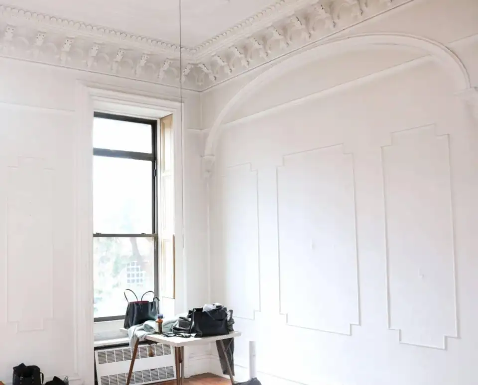
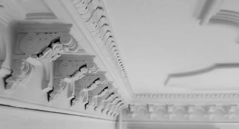
This project, seeking Passive House certification, is being constructed by Andrew Fishman and his company SMR Craftworks. The house is in relatively great shape with original plaster crown mouldings at the parlor level still intact. Both the owners and our team felt strongly this should be preserved so we developed a detail to leave the original crown moulding in place. The obstacle was to get the air barrier around a 16” plaster crown.
In addition to the plaster crown, the existing subfloor, 1” thick pine planks, was in such good shape that it would have been wasteful to remove and replace it. We agreed to protect it and refinish it as the final finish flooring. This added another challenge: creating an air seal that could be installed without removing any of the interior joists and disrupting the existing subfloor.
How do we secure the first joist, create an air barrier transition, and frame an interior wall while keeping the historic plaster crown in place and working within limited space of the second joist 12–16” away? The solution came about through many field sketches and brainstorming along side Andrew’s lead Super, Billy Edwards and our PH Consultant, John Mitchell of bldgtyp. SMR Craftworks chose to use the Pro Clima line of products and sourced this from 475 High Performance Building Supply. 475 has been working closely with SMR, often dispatching technicians to the site to demonstrate installation and field any installer questions.
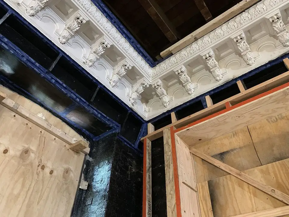
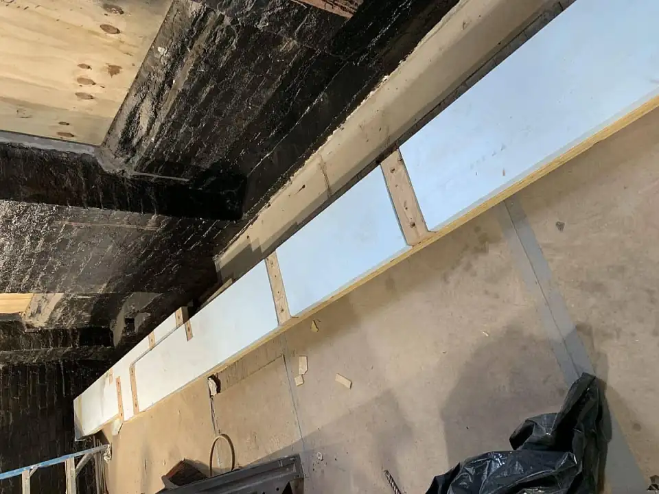
At the crown, the first order of business was to support the crown so that the wall framing could be removed to make room for installation of the liquid applied air barrier. SMR came up with the clever solution. Working in sections, they removed the wall framing, prepared the masonry near the crown, and installed a plywood shelf to support the crown. Later, when the air barrier installation is complete, wood framing will connect to the bottom side of plywood shelf.
As we’ve learned on past projects, sound plaster is airtight. With no room to install our air barrier behind the crown moulding, we opted to utilize the crown itself as part of the air barrier system. The plywood holding the crown in place was sprayed with Visconn and taped to the bottom edge of the plaster moulding. The top edge of the crown was connected back to the Visconn air barrier at the masonry wall with either plywood (installed between and sealed to the joists) or Intello membrane.
In the image above you can see a corner of this house that connects the two exposed facades (South and West) where the interior framing is complete on the west side and yet to be complete on the south. With all of this careful preparation, the final connection of the vapor retarder is simple: the Intello membrane along the wall will be taped to the underside of the crown. On the floor above, the Intello membrane connects to the plywood blocking used to connect the crown moulding back to the masonry wall.
Finding solutions to these challenges like this one where the solution does not subjugate the design, rather allows the design of space the drive the detailing is incredibly rewarding. Being on site with a highly talented group of consultants and builders is something we as a firm enjoy tremendously.
Note: All details included in this article were part of a completed design with a Certified Passive House Consultant and implemented by certified Passive House Tradespeople. Please consult your individual professionals and carefully consider your specific conditions on all projects.